|
Welcome to the 4th part of this Bioburden contamination Investigation! Part 1, Part 2, and Part 3 emphasized this investigation’s importance, what was going wrong, and how we should have thought about the problem. I haven’t been too clear on order of events, so let’s catch up on that. The site ran 3 Engineering runs without contamination. Run 4 was overgrown with Bioburden (Bacillus). The investigation blamed the use of a pool skimmer in the pooling vessel. Run 5 was also overgrown with Bacillus. During this month-long investigation:
Commercial Runs 1 and 2 ran back to back within a week. Run 1 had elevated Bacillus recovery, but below the established limit. Run 2 was OOL. New SMEs were brought in from sister sites. More swabbing was performed, and the team spent more time looking into bottle prep activities as the organism’s source. Another contractor cleaning was planned before run 3. The team was running out of clues but needed to wrap up the investigation. We didn’t have a choice; we would close the investigation and blame our best guess by run 3's planned start date. Less than a week before the investigation due date, the team was ranking which part of the bottle prep process was the most likely culprit. My mind was wandering to the cleaning validation results. Rinse samples were collected from most of the the pre-run equipment cleanings as part of the Clean-In-Place (CIP) validation. A few had Bacillus recoveries. Validation and Engineering were happy with the results because they met requirements. But of all the investigational tests performed, these ones hinted the organism was in the equipment in its cleanest state. The Engineering and Validation groups gave a presentation on the equipment and CIP process early in the investigation. The investigation team (including me) were out of our element for this. The engineering diagrams looked like an old school Windows screen saver to me.  We trusted the presentation. It made sense cleaning was performed correctly. When we looked at the actual equipment it looked simple enough, like the diagram below. Product went in one direction from the thaw vessels to the pooling vessels. Product contact piping is highlighted in pink. 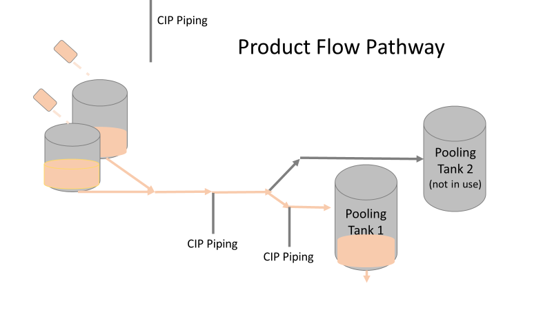 The cleaning process seemed just as simple. We saw where the CIP piping was connected to the thaw and pooling vessels. We also knew the thaw and pooling vessels couldn't be cleaned at the same time due to pathway overlap, So the team walked out of the presentation understanding the CIP paths looked like this: 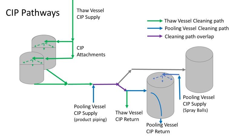 I spent a lot of time walking the product pathway in the mechanical areas. There were some valves and pipes that didn’t make sense to me. You can see those pipes circled below: 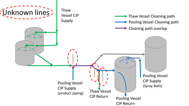 It bothered me not knowing what those pipes did. I asked the engineers. They didn’t seem concerned. They were CIP and drain pipes. This late in the investigation, I couldn't get a chance to talk out how they fit in the system. To help learn their fit- I pushed for a better rinse test than CIP samples. I was able to convince my manager to do exactly that test by talking him through the next diagram. CIP samples aren’t representative of every product contact piping section. It’s impossible to clean a tank by sending cleaning agents through the product inlet. To clean the tank, we use spray balls inside the tank lid. One CIP cycle runs through the product inlet, and a separate cycle runs through the tank spray balls. Rinse samples are collected from water that went through the spray ball pathway. These samples represent the cleanliness of the tank, the biggest product contact area. That means the test doesn’t tell us about the condition of the product inlet (circled in red below) 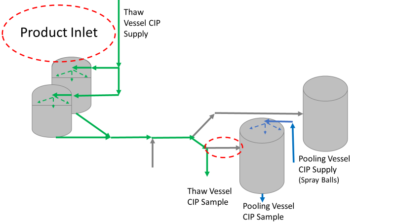 My manager presented the test idea to site leadership (I’m still a little salty I wasn’t given credit). After run 3, the equipment was CIP’d and rinse samples were collected from the green and blue paths above. We then altered the valve sequencing to send water through the green path below. 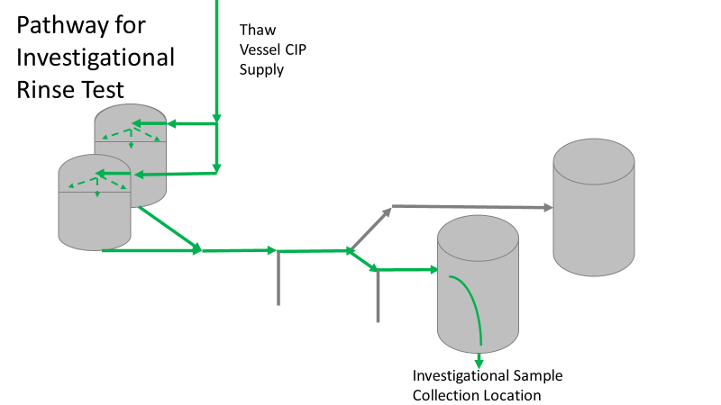 Run 3 bioburden results and the routine CIP rinse samples came back great. Site management started prepping raw material for run 4 thinking the investigation team figured it out. The investigational rinse samples were collected late enough that they were tested a day later. We convinced the production team to hold off starting run 4 until these results were ready. We were glad they did! These plates came back COVERED in Bacillus! They had to delay the start of run 4. So what happened? The results forced the engineering team into overdrive figuring this out. We were confident the product inlet section I circled was getting clean- we could tell water and cleaning agents were entering the tank through that inlet during the CIP cycle. As we looked further into the equipment I learned how the CIP actually worked. The thaw and pooling vessels had the same CIP source. To clean the thaw vessels, water flowed upstream from an entrance near the pooling vessel, diverted to non-product contact piping, then came back into the product pathway at the thaw vessel lid. 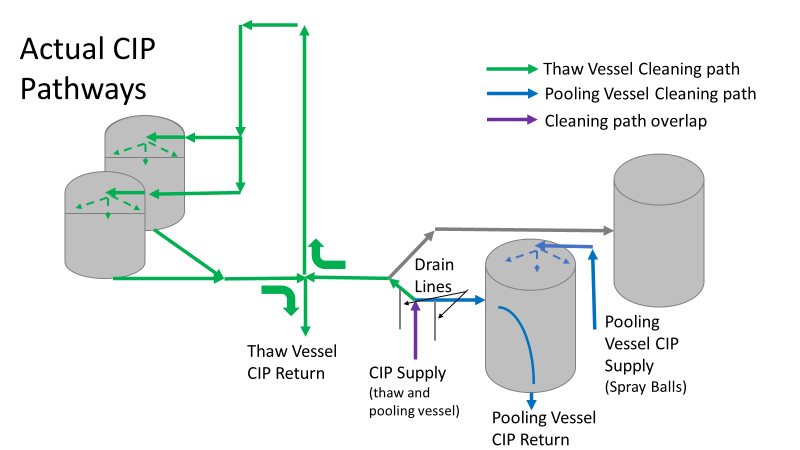 This was great! Well, not so great. This explains how a source of contamination in downstream pipes (where we had overgrown swabs) could spread to the top of the line. It also made us realize a mistake when we set up the system. There was a plan in place for scheduling the pooling vessels when the site was designed. Each pooling vessel would only receive raw material from a dedicated set of thaw vessels. The cleaning pathways were set up according to this plan. As a result, when the second set was used for the tank they weren’t dedicated to, a significant portion of the piping wasn’t getting cleaned. Broth residue remained in this spot between runs, growing the billions of bacteria needed for such huge bioburden recoveries. That section is circled in red here: 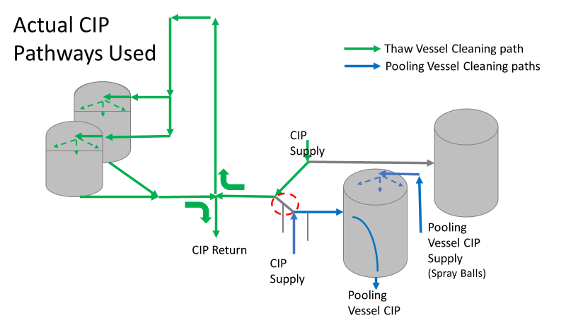 That still leaves a couple major questions.
1. How did the results meet requirements for run 3? The engineering team thought the contractor was using a better chemical to kill this spore-forming Bacilli. However, the contract cleaner couldn’t use the same CIP inlets for their cleaning agent. So, they had to manually adjust valves similar to how we ran the investigational testing. This allowed the contactor to clean all product contact piping. The cleaning process wasn’t as effective prior to commercial run 1 because there was so much time for the drain piping issue to impact the run… 2. What’s the drain piping issue, and why was Bacillus in the first set of thaw vessels? Drain valves throughout the line are opened after each product run and CIP. These openings allow residual broth to enter the drain line. There was no cleaning cycle to remove this broth from the drains. The drains pictured above lead to an ISO 8 space with high air pressure. Now imagine the draining process like you’re emptying a 2L soda bottle. Air gurgles into the bottle to replace the liquid. After the CIP, high pressure air pushes through the drain back into the product line, carrying any bacteria in the broth residue along the way. Now we have our two root causes:
We had to reject $2 million worth of raw material from commercial runs 1 and 2 to figure that out. Luckily, the last-minute test added between runs 3 and 4 saved the next million dollar batch. To correct these issues, all we did was alter the CIP cycles to clean the implicated areas. In part 5, I’ll show how we failed on the follow through.
0 Comments
Leave a Reply. |
